
 Contatti
- CYPE >
- italiano >
- servizi >
- area download >
- 2022.g
Novità della versione 2022.g
INDICE
NOVITÀ NEI PROGRAMMI ESISTENTI
- New features common to several programs
- Implementing codes and improving their enforcement
- CYPE Architecture
- Open BIM Site
- Topographic surface by points
- Editing the points of a topographic surface
- Exporting a topographic surface to a points file
- Projecting maps on a topographic surface
- Type and calculation of the number of points on a topographic surface
- Simplifying a topographic surface
- Editing tools for topographic surfaces
- Improved display of contour lines
- Open BIM Analytical Model
- CYPECAD
- Exporting quantities related to structural elements to the BIM model in order to facilitate their measurement
- Exporting of reinforcement bars of concrete walls to BIM model
- Embedded beams in concrete walls
- Service class of timber elements
- Punching shear. Supports with slabs in different levels
- Other improvements and corrections
- CYPE 3D
- CYPE Connect / Open BIM Layout
- CYPE Connect
- CYPELEC Electrical Mechanisms
- CYPEPLUMBING Water Systems
- CYPEHVAC Ductwork
- Open BIM Quantities
- Tornare all'area download della versione 2022
NOVITÀ DEI PROGRAMMI ESISTENTI
New features common to several programs
Programs included in the Open BIM workflow
Further information on the BIMserver.center project
The following fields have been included in the BIMserver.center project information panel linked to the job:
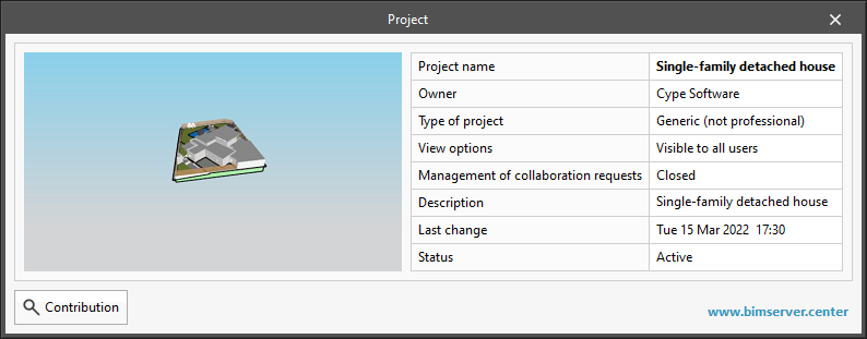
- Owner
Indicates the name of the BIMserver.center user who owns the project. - Last change
Indicates the date on which the last change was made to the project. - Status
Indicates the status of the project. Projects that are not "active" will not be able to receive any new contributions.
Additionally, a button has been added to display the contributions in the project, as well as the files that they contain.
Project data in the panel linked to BIMserver.center
The following columns have been included in the project selection table on the BIMserver.center platform:
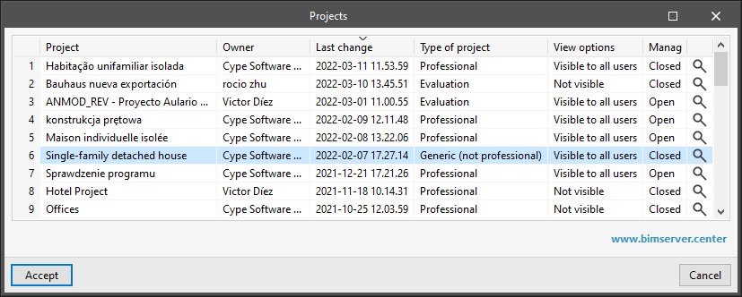
- Type of project
Indicates the type of project according to the classification of the BIMserver.center platform. - View options
Indicates whether the project is visible to the rest of the users of the BIMserver.center platform or only to the members of the work team. - Management
Indicates whether the project is open to collaboration requests from other users of the BIMserver.center platform.
Additionally, a button has been added to display the contributions in the project, as well as the files that they contain.
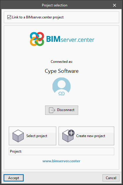
Changing the user account when linking to a BIMserver.center project
As of version 2022.g, applications that can be linked to a project on the BIMserver.center platform allow the user account to be changed during the project selection process. To do this, a "Disconnect" button has been added next to the user’s name and image in the "Project selection" panel. When disconnecting the active account, the credentials of the account (e-mail and password) that the user wishes to work with can be entered.
Applications with a 3D environment
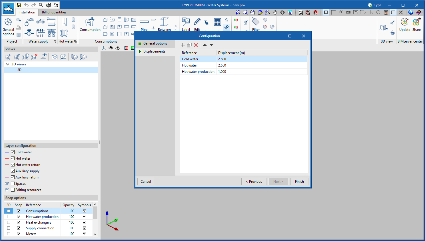
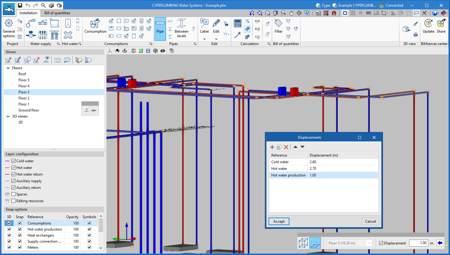
Defining displacements
In applications with a 3D working environment, a new tool has been added to the configuration bar which is displayed when adding or editing the position of an element. This option appears as a button on the right-hand side of the "Displacement" field and allows users to define displacements associated with each view of the project. By clicking on this button, a list is displayed where the displacement values can be entered together with an associated reference in order to easily identify them. When the panel is accepted, the selected value is automatically assigned to the "Displacement" field.
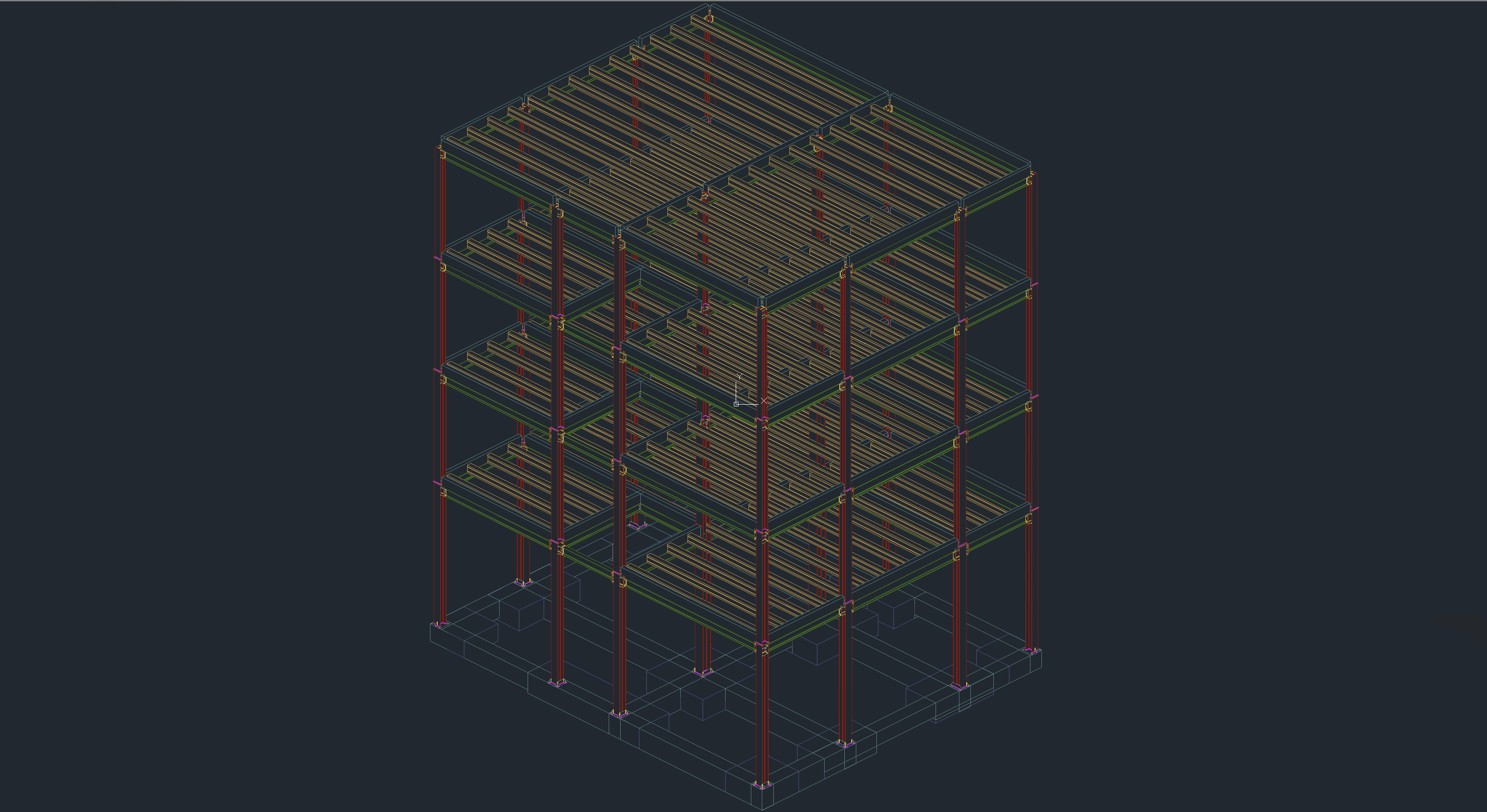
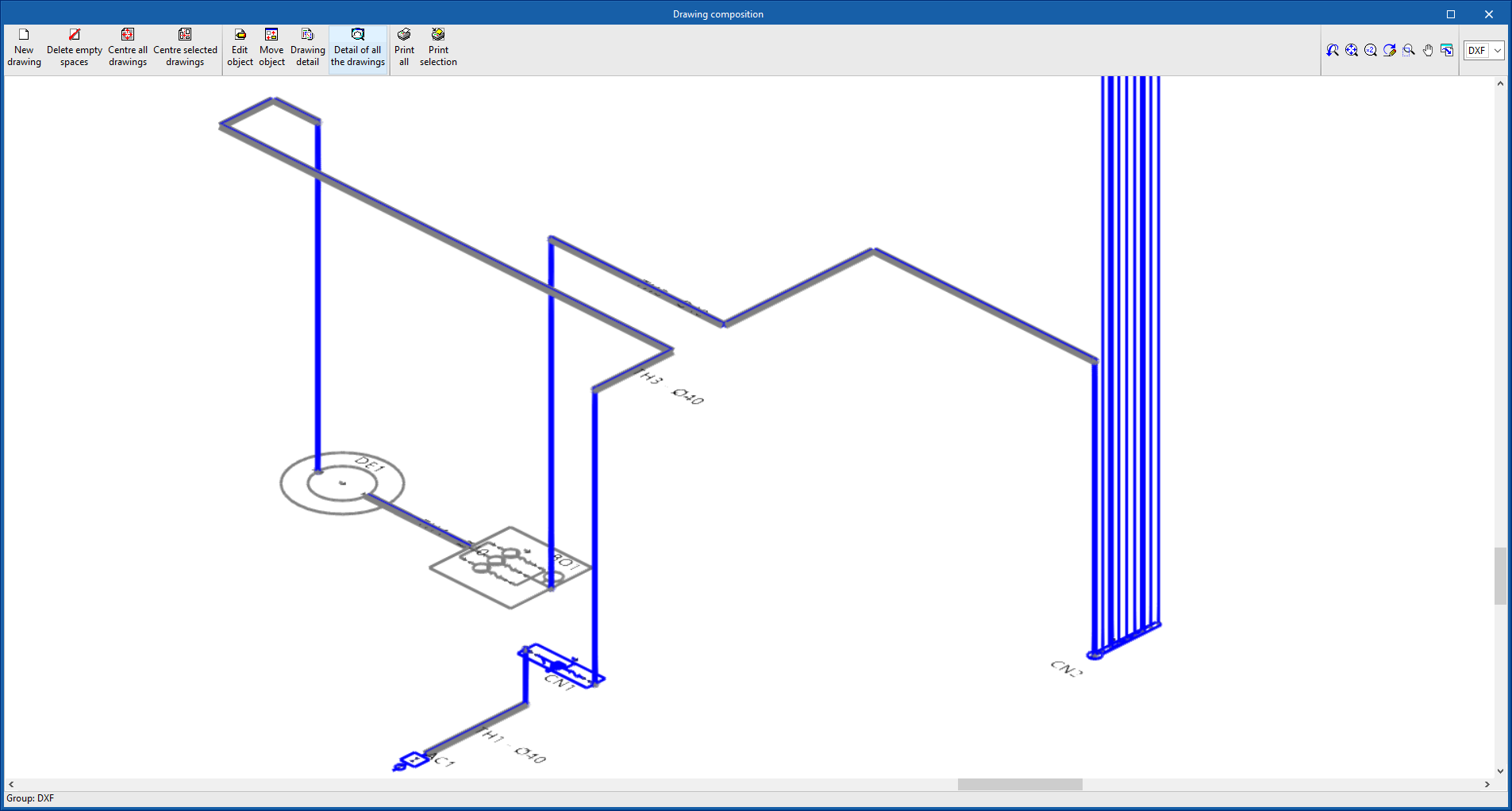
Exporting 3D views to 2D DXF and DWG formats
The options for exporting 3D views to 2D DXF and DWG formats have been implemented. The dialogue box containing these new options can be accessed from the "Print the current view" button, in the top bar of the 3D views.
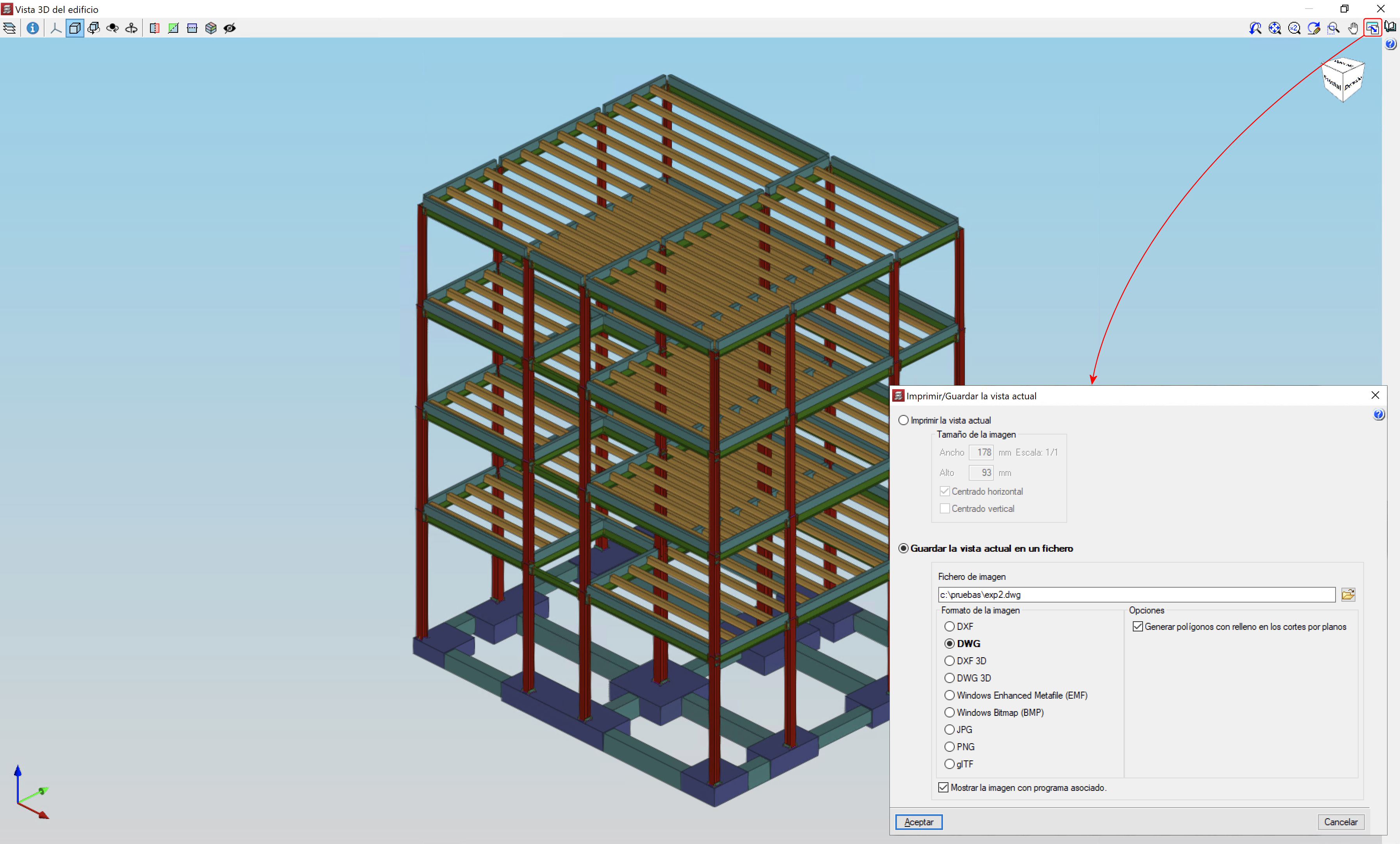
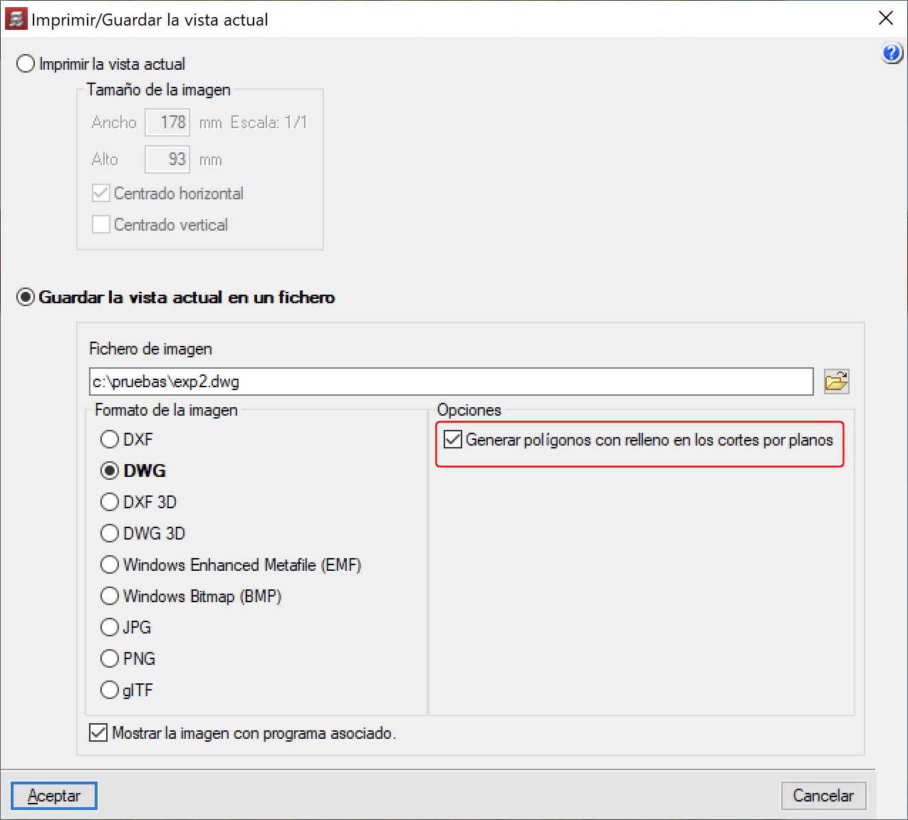
If a scene has defined cutting planes or volumes, filling polygons can be generated on the elements that are cut by these planes or volumes.
This can be carried out by activating the "Generate polygons with filling in the cuts by planes" option.
Implementing codes and improving their enforcement
Connections for steel structures
Implementation. PN-EN 1993-1-8:2006/NA:2011 (Poland)
The Polish National Annex to Eurocode 3 ("Design of steel structures – Part 1-8: Design of joints") for the design of joints in steel structures has been implemented into the following programs:
- CYPE 3D
- CYPE Connect Classic
CYPE Architecture
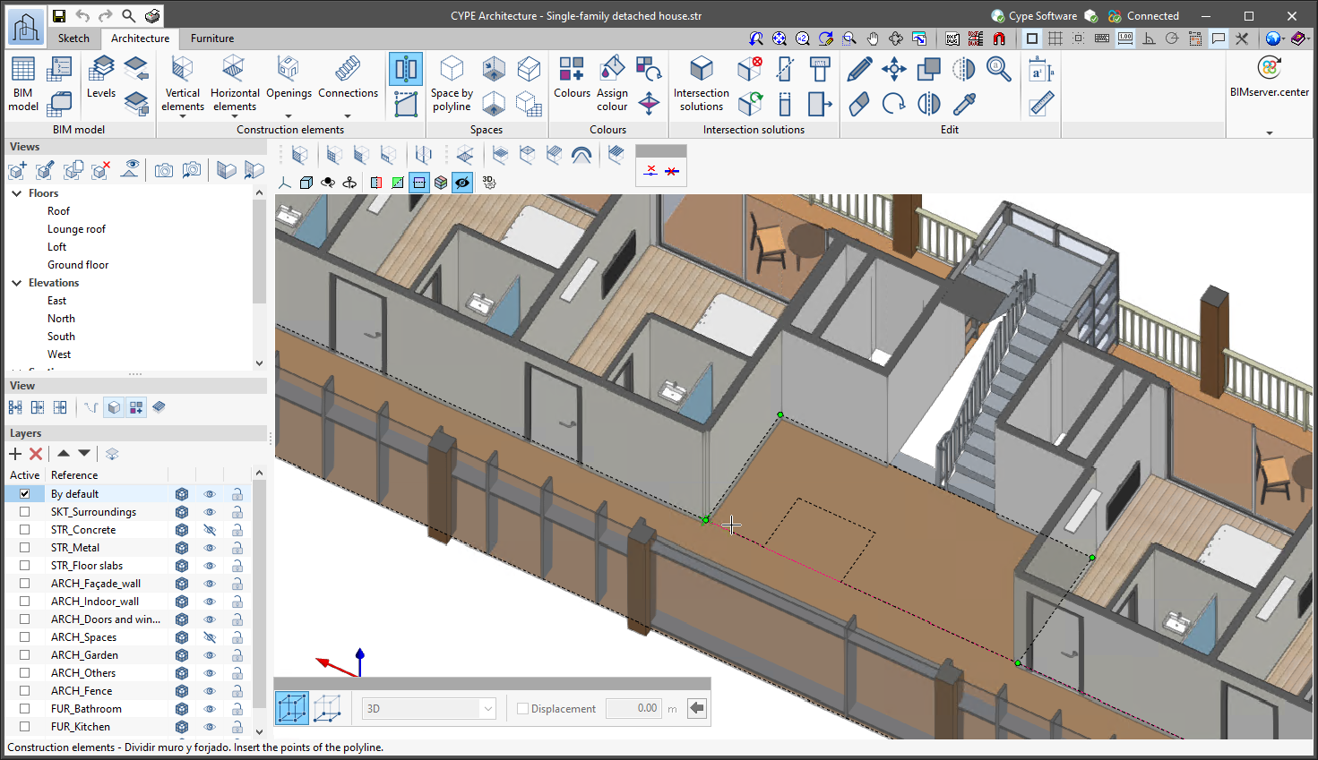
Dividing walls and floor slabs
Version 2022.g includes a new tool for dividing walls and floor slabs that have already been entered in the model. The way this tool operates depends on the type of element being divided:
- For walls
They are divided by a line defined by two points. - For floor slabs
They are divided by a polyline defined by as many points as the user desires.
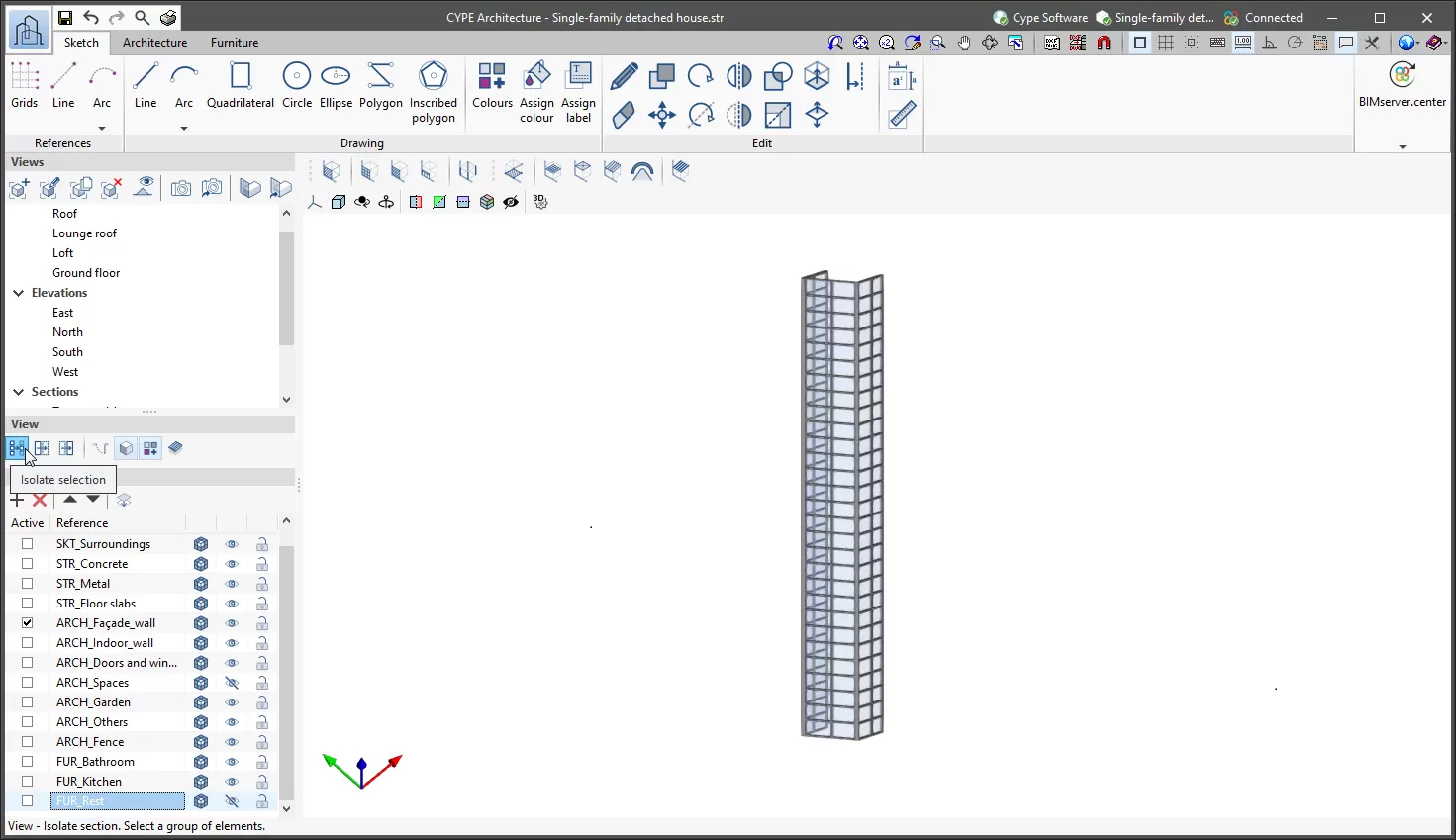
Isolating elements
In version 2022.g of CYPE Architecture, the "Isolate selection" tool has been implemented and is located in the "View" panel of the left sidebar. This tool can be used to select a series of elements so that they remain visible, while those not selected will remain hidden.
Exporting only visible elements to the BIM model
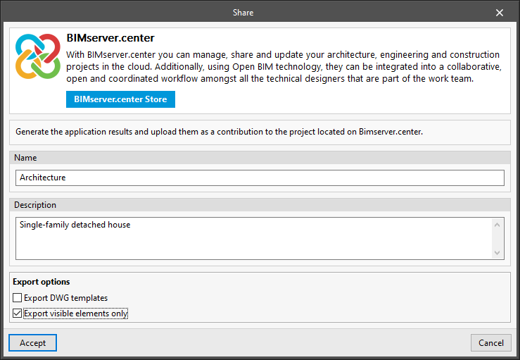
A new feature has been implemented to export only visible elements to the linked BIM project in the BIMserver.center platform.
This feature only exports the elements that are visible in the program when the export is carried out. Any elements that are hidden using any of the modes available in CYPE Architecture will not be exported to the BIM project, providing greater flexibility when sharing models.
This export (only visible elements) allows users to draw more than one model on the same job and export what is required to the BIM project without the need to delete anything, thus transforming the CYPE Architecture interface into a workspace for design.
For example, in a refurbishment project, the same CYPE Architecture job could include a model of the building that represents its state before the refurbishment and another model that represents its state once it has been refurbished. With the feature for exporting only visible elements, both models could be shared separately on the BIMserver.center platform. Even if some of the models or some of the elements of a model have not been drawn in their position in CYPE Architecture, they can be exported to the BIMserver.center platform in the desired position if the geolocation is modified locally when exporting them.
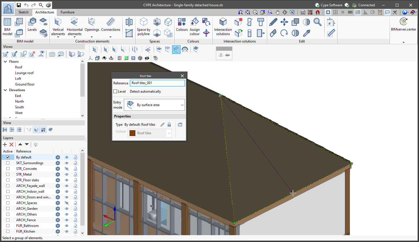
Improvements in the "Roof tiles" feature
The "Roof tiles" feature includes the following improvements:
- Roof tiles by surface area
To draw the roof tiles, by surface area must be selected, followed by the direction of the roof tiles by clicking on two points on the screen. - Openings in the roof tiles
The "Openings" tool can be used to create openings in the roof tiles.
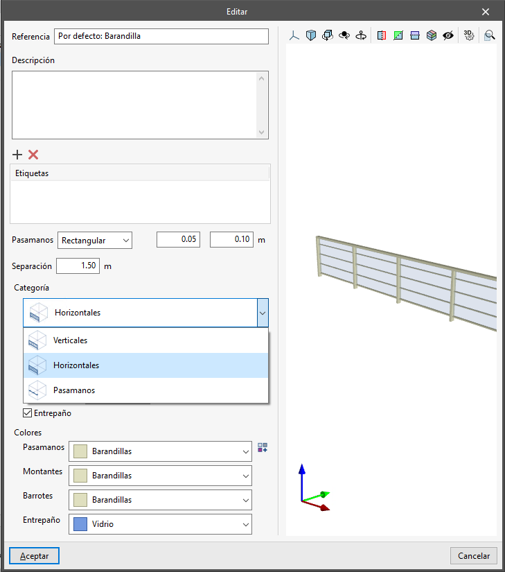
Improvements for railings
Another category has been added to the railings: "Horizontal".
Furthermore, the design of railings and stair railings has been unified. In both features, there are now three categories: "Horizontal", "Vertical" and "Handrail".
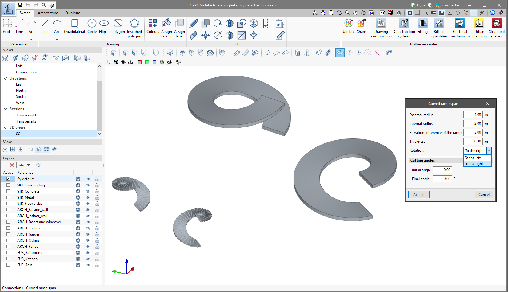
Rotation in curved ramps and spiral stairs
The "Rotation" option has been included for curved ramps and spiral stairs.
With this option, the rotation direction of these elements can be changed (to the left or to the right) during both introduction and editing.
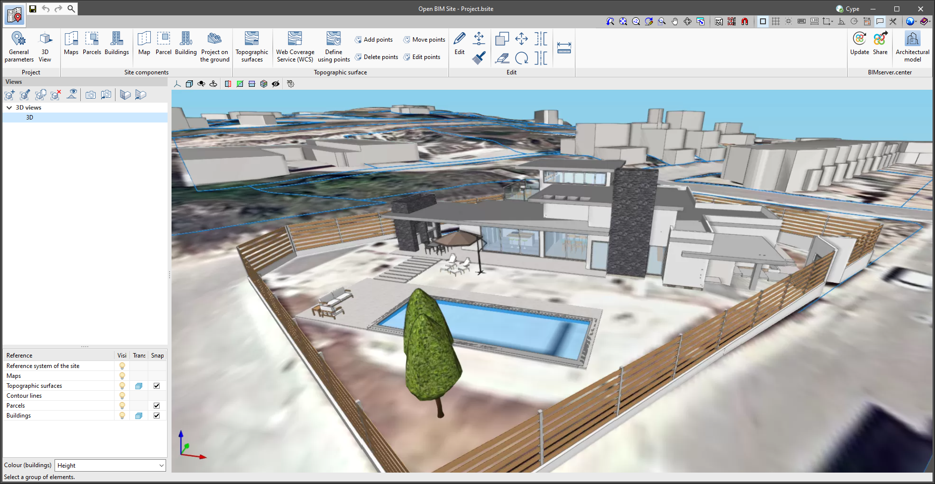
Open BIM Site
Topographic surface by points
As of version 2022.f, Open BIM Site allows a topographic surface to be entered by placing topographic points on the work area. To do this, the "Define using points" button has been added within the "Topographic surface" group available in the application’s toolbar.
Once the points have been entered, the application will automatically generate the surface and it will be added to the list of the project’s topographic surfaces.
Editing the points of a topographic surface
As of version 2022.g, the points forming the topographic surfaces of the project can be modified. For this purpose, the following options have been added to the application’s toolbar.
- Add points
It allows the user to select an existing topographic surface and add new points to its configuration. - Delete points
It deletes one or several points belonging to the topographic surfaces of the model. - Move points
It allows the user to edit the position of one or several points belonging to the topographic surfaces of the model. - Edit points
It allows the user to edit the elevation of one or more points belonging to the topographic surfaces of the model.
The "Add points", "Delete points" and "Move points" tools can only be used on "Mesh" type topographic surfaces. "Grid" type topographic surfaces, usually imported from Web Coverage Services (WCS), can be transformed into meshes using the tool for simplifying surfaces (see new feature "Simplifying a topographic surface").
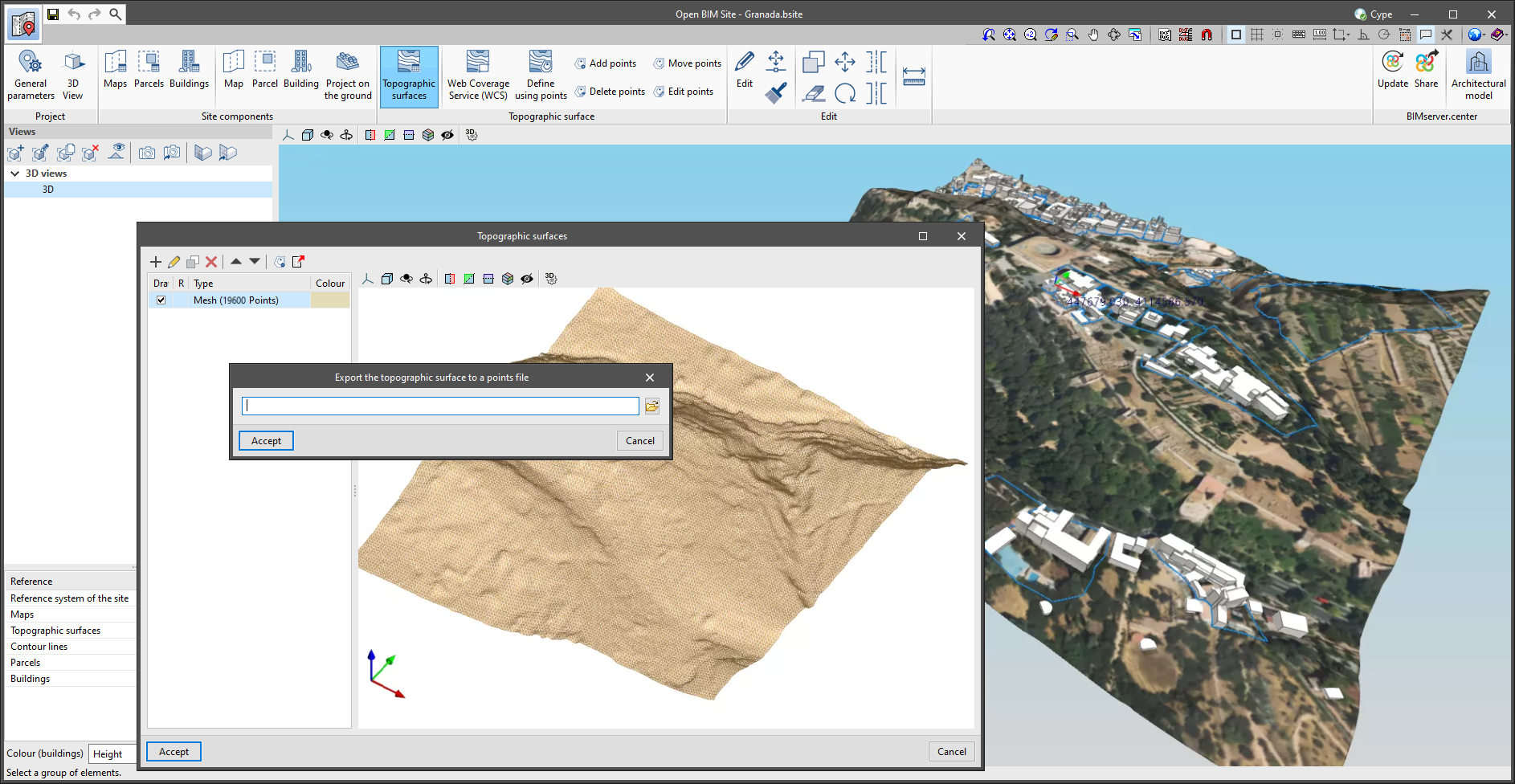
Exporting a topographic surface to a points file
A button has been added to the project’s topographic surface table, available in the application’s toolbar, for exporting the selected surface to a points file. The export format is a comma-delimited value file with the X, Y, Z coordinates of each point on each line.
Projecting maps on a topographic surface
The "Topographic surface" column has been added to the project maps table, available in the application’s toolbar. For each map, a topographic surface can be selected where the map will be projected and displayed in the drawing area as a texture. If the "Without associated surface" option is selected, the map will be drawn at zero level, as in previous versions of the application.
Type and calculation of the number of points on a topographic surface
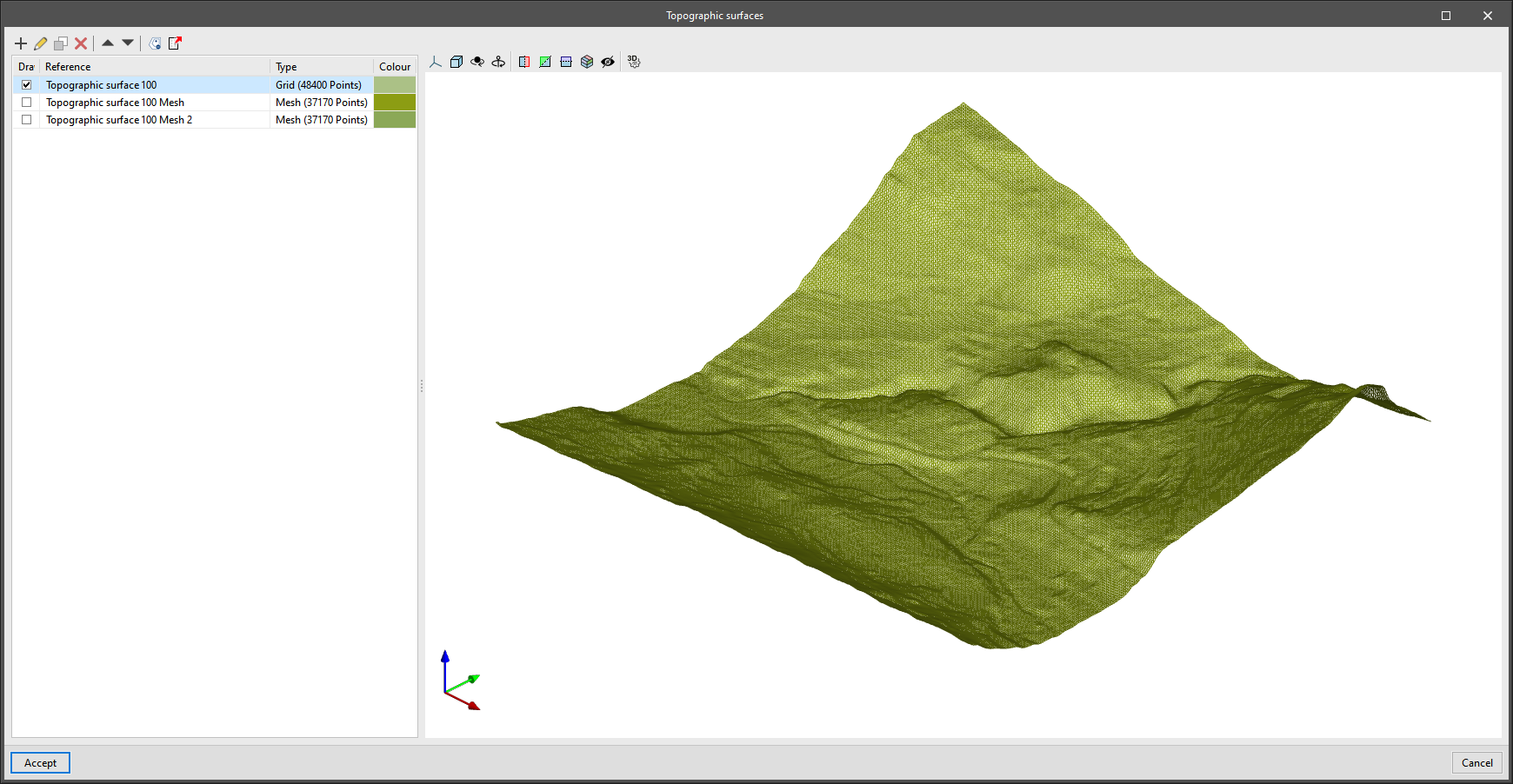
The "Type" column has been added to the project’s table of topographic surfaces, available in the application’s toolbar. In this new field, users can indicate whether the surface has either a "Mesh" or a "Grid" type definition. A "Grid" type topographic surface is defined by points arranged on the basis of a grid, whereas a "Mesh" type topographic surface is composed of vertices that are arranged without an organised structure. "Grid" type surfaces are more efficient when represented on the drawing area of the program, as the triangulation process has a lower computational cost. However, the points that make up this type of surface cannot be added or edited from Open BIM Site.
Along with the type of the topographic surface, the number of points that define it is also displayed.
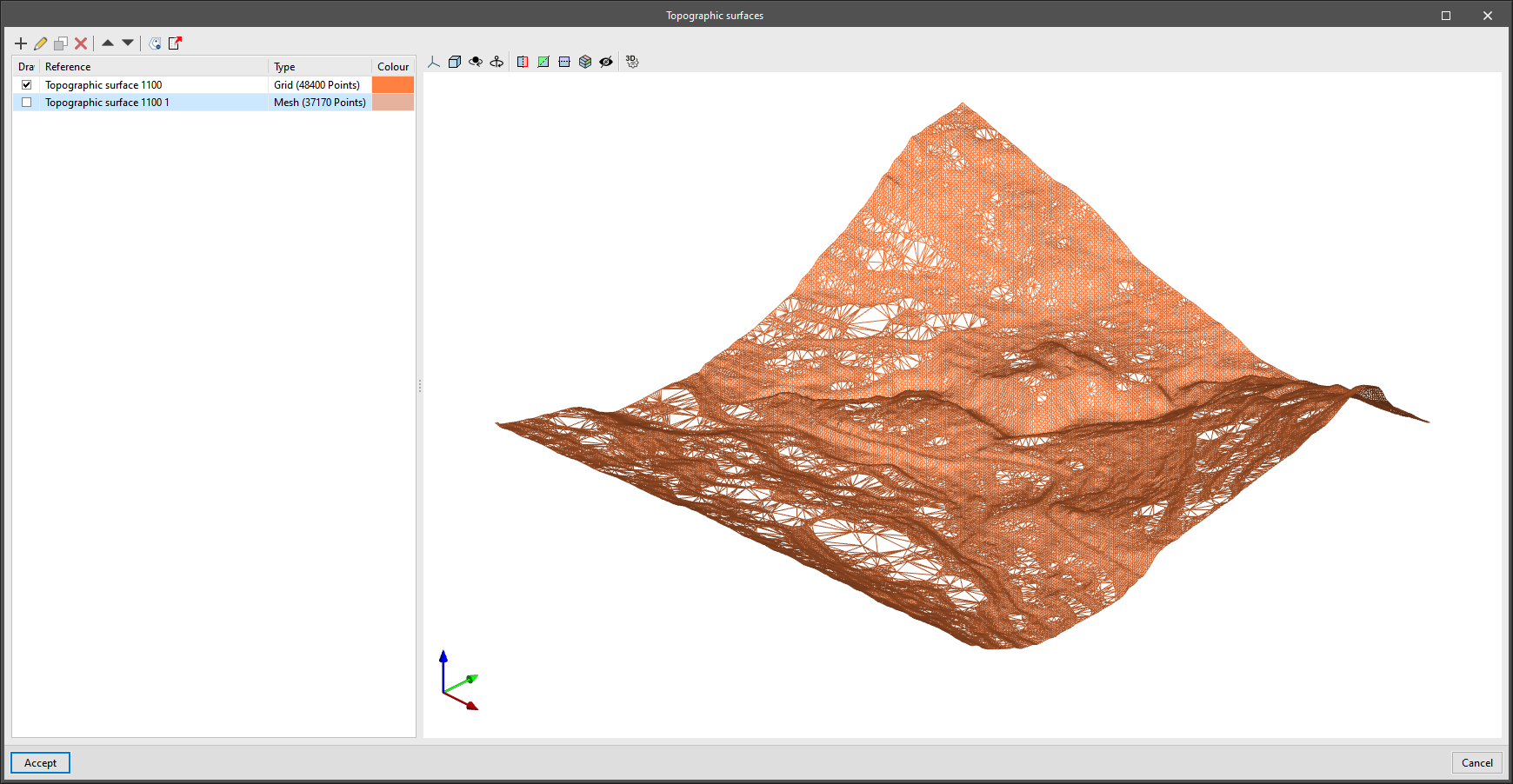
Simplifying a topographic surface
As a consequence of the computational cost of triangulating topographic surfaces, a tool has been added to simplify the number of points they contain and thus increase the performance of the application. This option is available in the project’s table of topographic surfaces, available from the application’s toolbar.
Once the simplification process has been completed, users are advised to review the result and increase its accuracy by editing the topographic points if necessary.

Editing tools for topographic surfaces
As of version 2022.g, the following tools from the "Edit" menu of the toolbar can be used on the topographic surfaces of the model:
- Edit
- Copy
- Delete
- Move a group of elements
- Rotate a group of elements
- Symmetry (move)
- Symmetry (copy)
- Measure
In order to be able to use the reference to objects on topographic surfaces, the "Capture" option has been added to the components list of the site model to capture this type of elements.
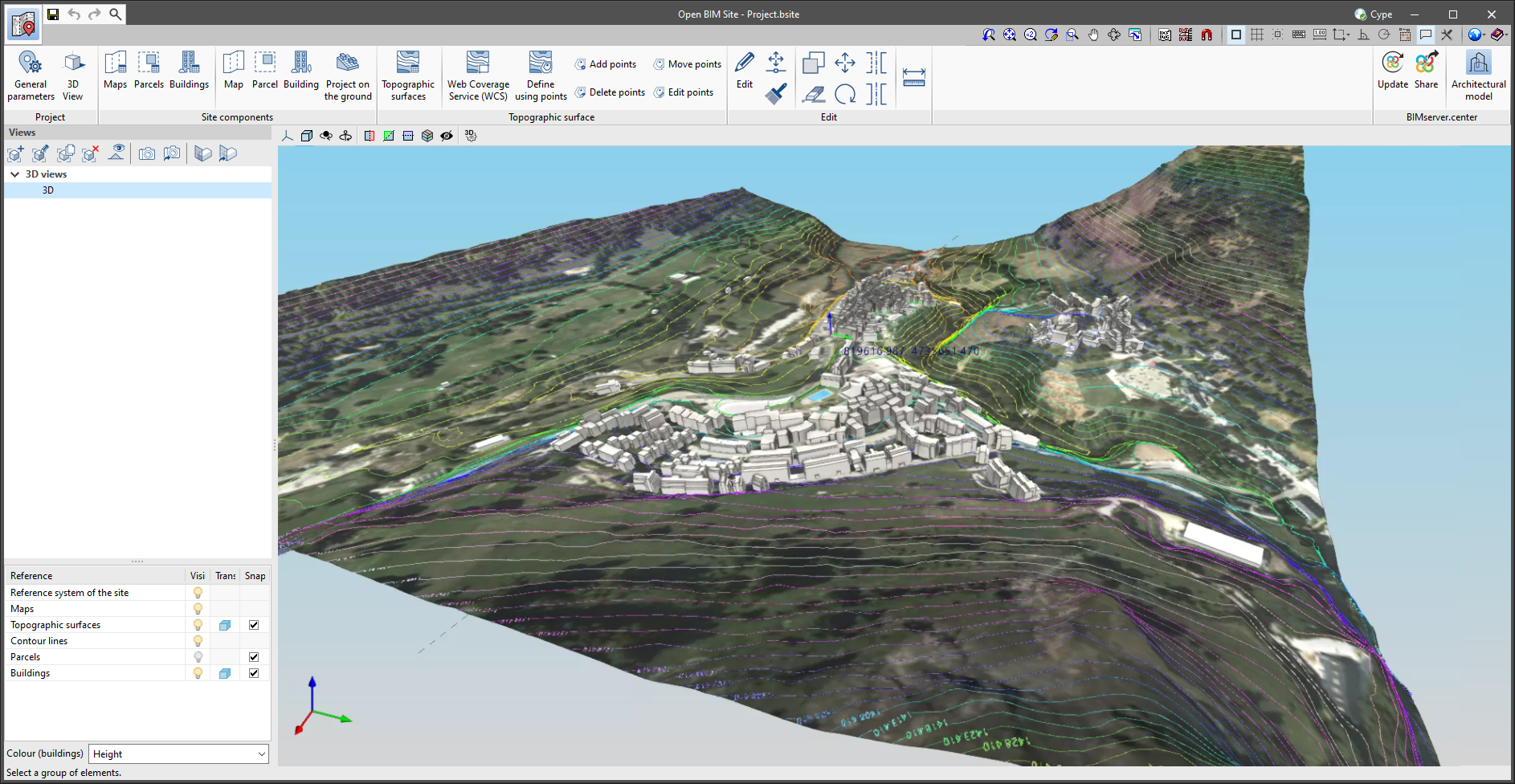
Improved display of contour lines
The drawing of contour lines has been improved. In the previous version of the application, the representation of contour lines could interfere with topographic surfaces when they were active.
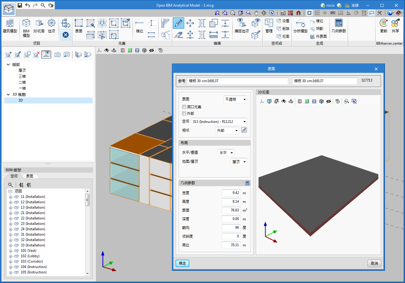
Open BIM Analytical Model
Installation in Chinese
As of version 2022.g, Open BIM Analytical Model can also be installed in Chinese.
CYPECAD
Exporting quantities related to structural elements to the BIM model in order to facilitate their measurement
CYPECAD exports a BIM model to a project on the BIMserver.center platform which includes the quantities related to certain structural elements, among other things. As a result, programs such as Open BIM Quantities can use these quantities to generate the bill of quantities for these elements. These quantities are exported using the standardised IFC format.
In version 2022.g, the number of quantities associated with construction elements that can be exported has been extended. CYPECAD now exports the following quantities, which are listed by construction element and indicating the IFC entity that it contains:
- Walls (entity "IfcWall", set of quantities "Qto_WallBaseQuantities")
- Length ("Length")
- Width ("Width")
- Height ("Height")
- Gross footprint area ("GrossFootprintArea")
- Net footprint area ("NetFootprintArea")
- Gross side area ("GrossSideArea")
- Net side area ("NetSideArea")
- Gross volume ("GrossVolume")
- Net volume ("NetVolume")
- Slabs ( entity "IfcSlab", set of quantities "Qto_SlabBaseQuantities")
- Width ("Width")
- Length ("Length")
- Depth ("Depth")
- Perimeter ("Perimeter")
- Gross area ("GrossArea")
- Net area ("NetArea")
- Gross volume ("GrossVolume")
- Net volume ("NetVolume")
- Gross weight ("GrossWeight")
- Net weight ("NetWeight")
- Beams (entity "IfcBeam", set of quantities "Qto_BeamBaseQuantities")
- Length ("Length")
- Cross section area ("CrossSectionArea")
- Outer surface area ("OuterSurfaceArea")
- Gross volume ("GrossVolume")
- Net volume ("NetVolume")
- Columns (entity "IfcColumn", set of quantities "Qto_ColumnBaseQuantities")
- Length ("Length")
- Cross section area ("CrossSectionArea")
- Outer surface area ("OuterSurfaceArea")
- Gross volume ("GrossVolume")
- Net volume ("NetVolume")
- Footing (entity "IfcFooting", set of quantities "Qto_FootingBaseQuantities")
- Length ("Length")
- Width ("Width")
- Height ("Height")
- Gross volume ("GrossVolume")
- Net volume ("NetVolume")
- Gross weight ("GrossWeight")
- Net weight ("NetWeight")
- Piles (entity "IfcPile", set of quantities "Qto_PileBaseQuantities")
- Cross section area ("CrossSectionArea")
In order to export the quantities, the complete analysis of the job must be carried out and the "Quantities" option must be selected in the "Share" dialogue box, which appears when clicking on the "Share" option in the "BIMserver.center" menu.
Exporting concrete wall reinforcement bars to the BIM model
CYPECAD version 2022.g allows the reinforcement of concrete walls to be exported to the BIM project.
Therefore, the concrete elements that export their reinforcement to the BIM project up to this version are:
- Concrete walls
- Beam frames
- Columns
- Corbels
- Foundation elements
Footings, pile caps, strap beams and tie beams. - Floor slabs
Joist floor slabs, waffle slabs, hollow core plate floor slabs, composite slabs and flat slabs.
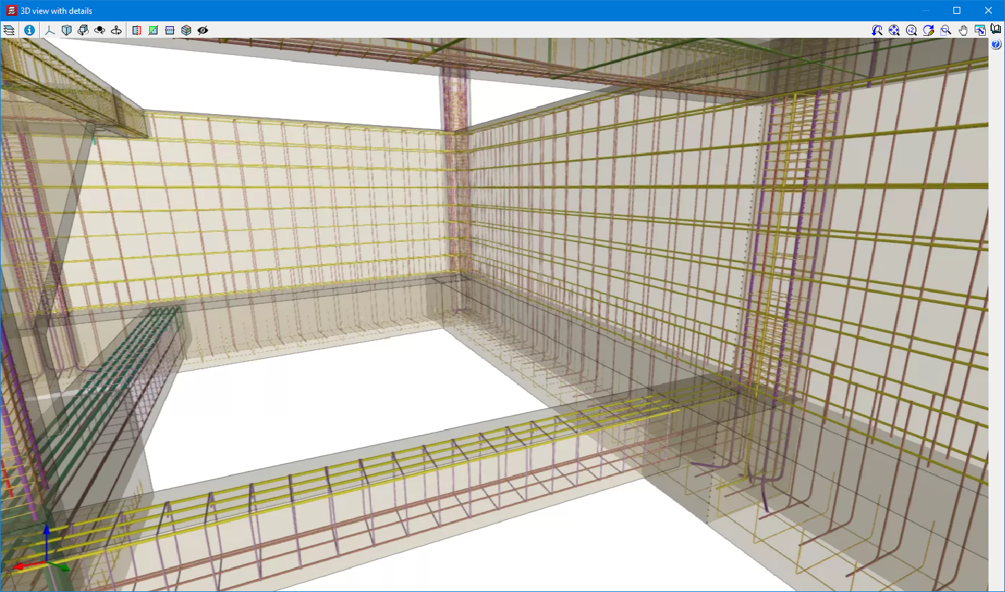
This reinforcement, along with the reinforcement exported from StruBIM Shear Walls, can be viewed in the StruBIM Rebar program.
They can also be viewed in the "Results" tab (Groups menu > 3D view with details).
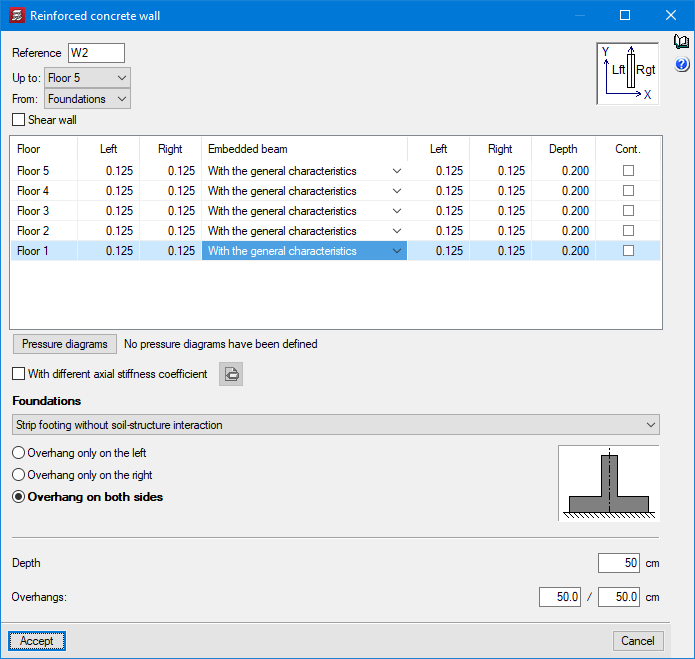
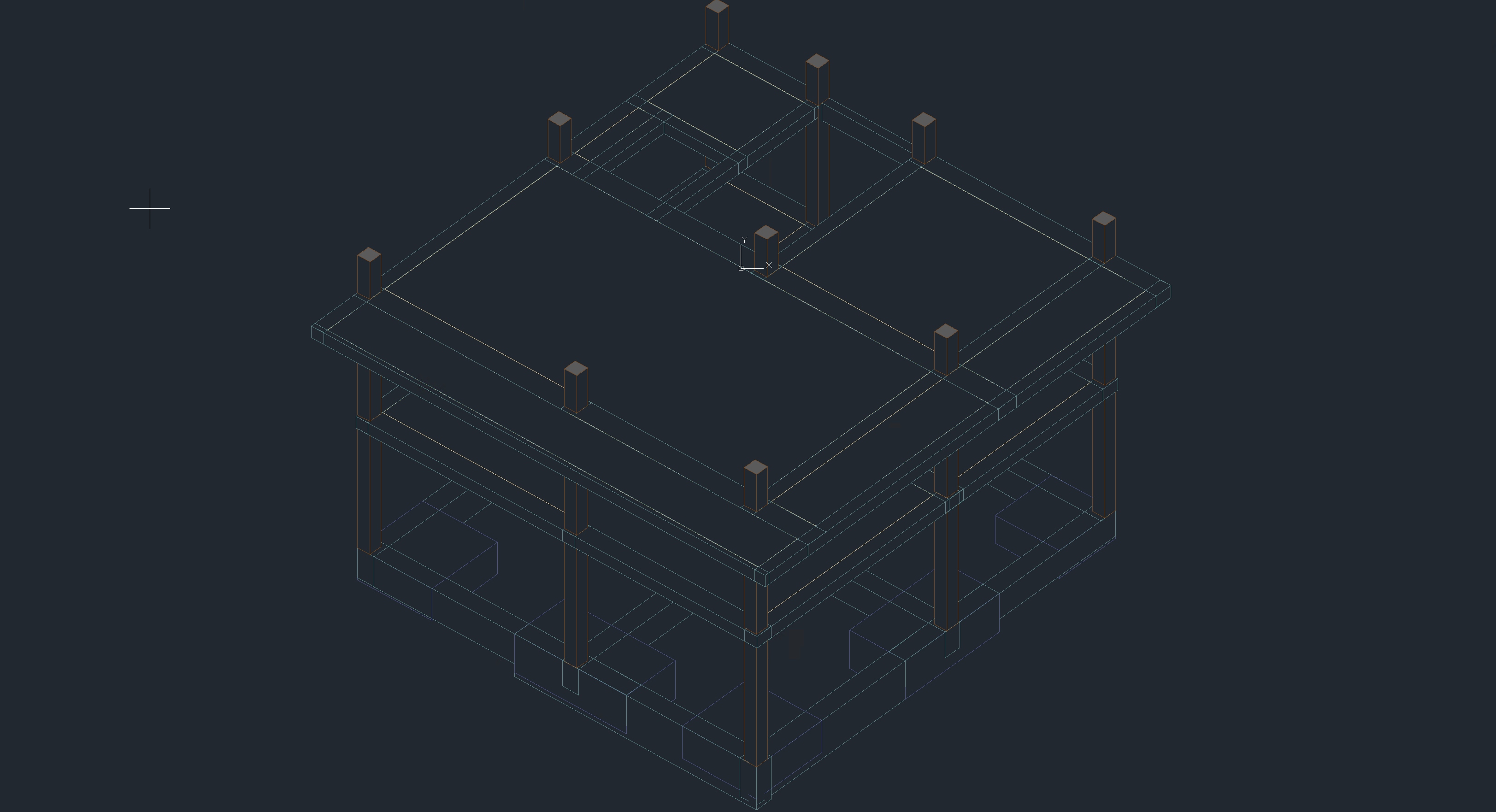
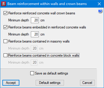
Embedded beams in concrete walls
In previous versions, crown beams could be defined in concrete walls. As of version 2022.g, embedded beams can also be defined at the level of each intermediate floor.
Service class of timber elements
As of version 2022.g, the service class can be defined individually for each timber element (columns, beams and joist floor slabs).


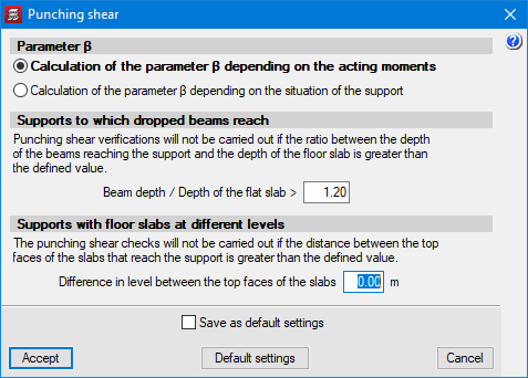
Punching shear. Supports with floor slabs at different levels
In the "Flat, waffle and joist floor slab options" – "Punching shear" ("Project" menu > "General data" > steel bars "By position" button), the difference between the top surfaces of the floor slabs can be defined in order to carry out the punching shear check in the same way as if they were at the same level. If the distance between the top surfaces of the floor slabs facing the support is greater than the defined value, the punching shear checks will not be carried out.
Other improvements and corrections
Version 2022.g of CYPECAD includes other minor improvements and corrections of the program that could occur in certain cases:
- Improvement in the "Forces in columns, shear walls and walls by loadcase" report
The "Worst case forces" column in the "Summary of code checks" table has been improved. As of version 2022.g, the worst case forces in the table include the minimum eccentricity and are amplified in order to take into account the second order effects caused by the slenderness of the column, in accordance with the code’s criteria. - Improved calculation of the dimensioned length of beam spans in the "Frame editor"
In some cases where two continuous beams with different widths meet, the span lengths displayed could be slightly longer than the actual span lengths. - Reinforced and prestressed joist floor slabs
An error that prevented reinforced and prestressed joist floor slabs from being imported in jobs where the Spanish structural code "Código Estructural" standard was selected has been fixed. - Improved shear wall removal
After deleting a shear wall in "Column Definition" its associated beams do not remain on the floors where it was defined unless it was in contact with a panel. - Check fire resistance of the current group
An error that occurred in the "Fire check of the current group" option if shear walls were defined in the job has been fixed. - Improvement in the "Tags > Assign" option
The joints reference is drawn in the "Show References > Joints" option is checked. - "Column forces and reinforcement" report
An error that occurred when obtaining the "Column forces and reinforcement" report if only generic columns were installed in the job has been fixed. - Checking column forces
An error that occurred when checking column forces in jobs that had only defined the foundation level has been fixed. - Improved calculation of reinforcement ratios for punching shear checks
The calculation of reinforcement ratios "ρx" and "ρy" in punching shear checks has been improved. In some cases, the base reinforcement was not taken into account correctly. Furthermore, as of version 2022.g, the default reinforcement is taken into account. - Improved punching shear checks
In the drop panels of waffle slabs, the checks are carried out on the perimeter corresponding to the area outside the punching shear reinforcement as long as this perimeter is completely enclosed by the drop panel. - Improved punching shear checks
After adding reinforcements, the reinforcement ratios are updated if there are changes in the critical perimeter. - Column reinforcement drawings
An error that occurred during the generation of drawings when the transverse reinforcement of a generic section column was not correctly defined has been fixed. - Improved import of beams from BIM models
When importing a BIM model with grouped beams, only the first one was imported. Now, they are all imported. - Updating the BIM model
An error that occurred when updating a BIM project after adding a floor with beams in the project has been fixed. - Sharing the BIM model
An error that occurred when selecting the "Share" option from "BIMserver.center" in the top menu has been fixed. The error occurred when inverted type reinforced joist floor slabs with a central edge value equal to 0 were defined in the job.
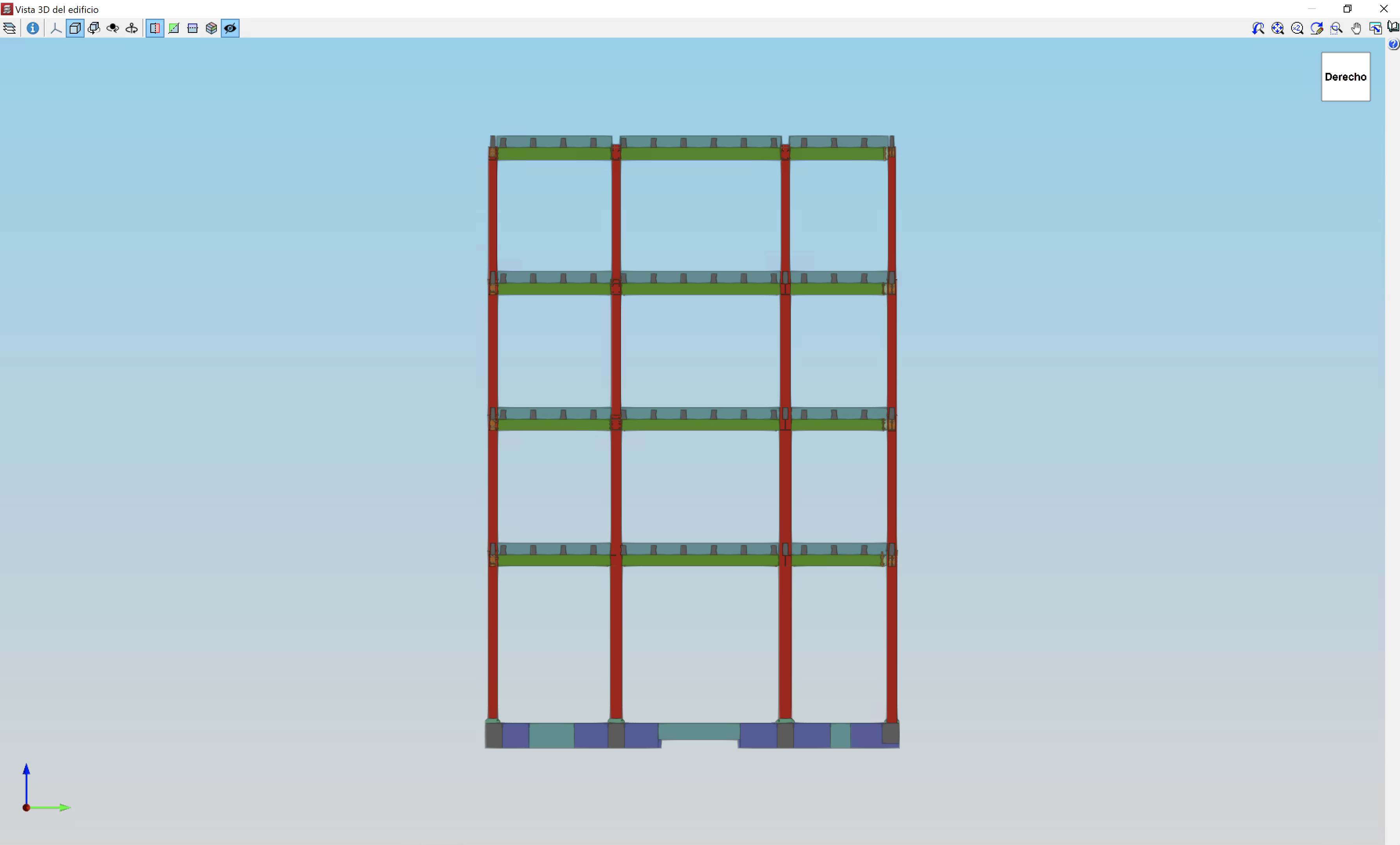
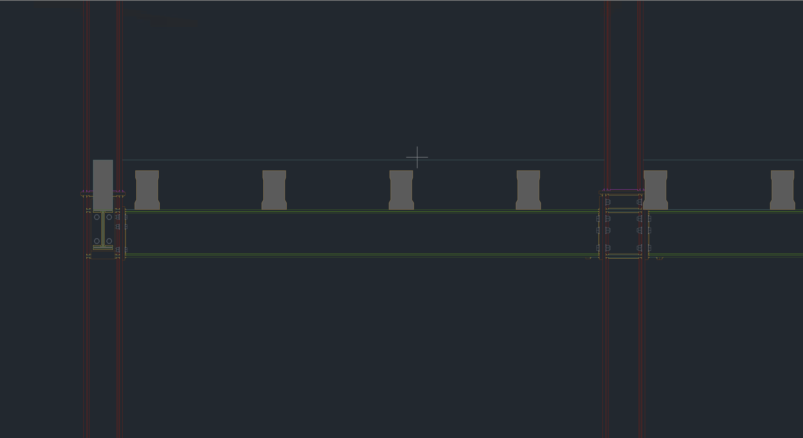
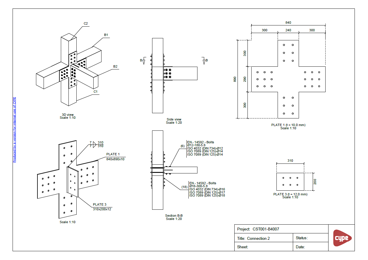
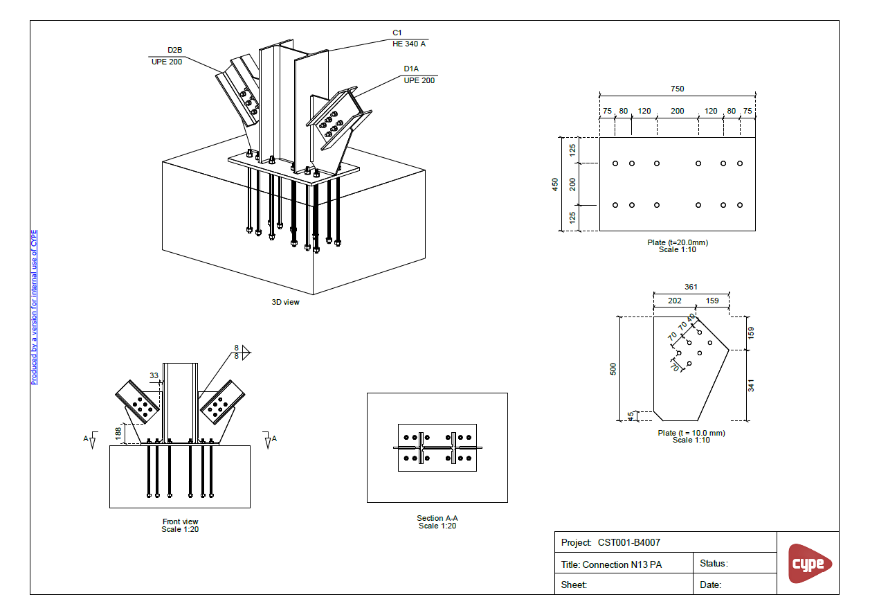
CYPE 3D
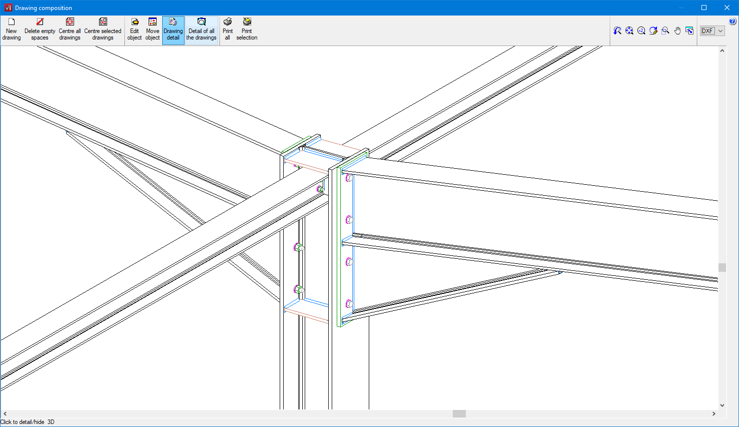
Improved drawing generation
In this version, the generation of structural drawings with an actual profile has been improved. The new implemented technique (multithreading) has reduced generation time by up to 90% (depending on the configuration of your computer) and also increases the robustness of the generation process.
Furthermore, both welds and bolts of the modelled connections can now be included in this type of drawing.

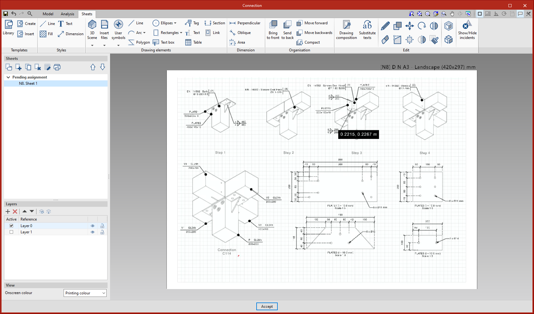
CYPE Connect / Open BIM Layout
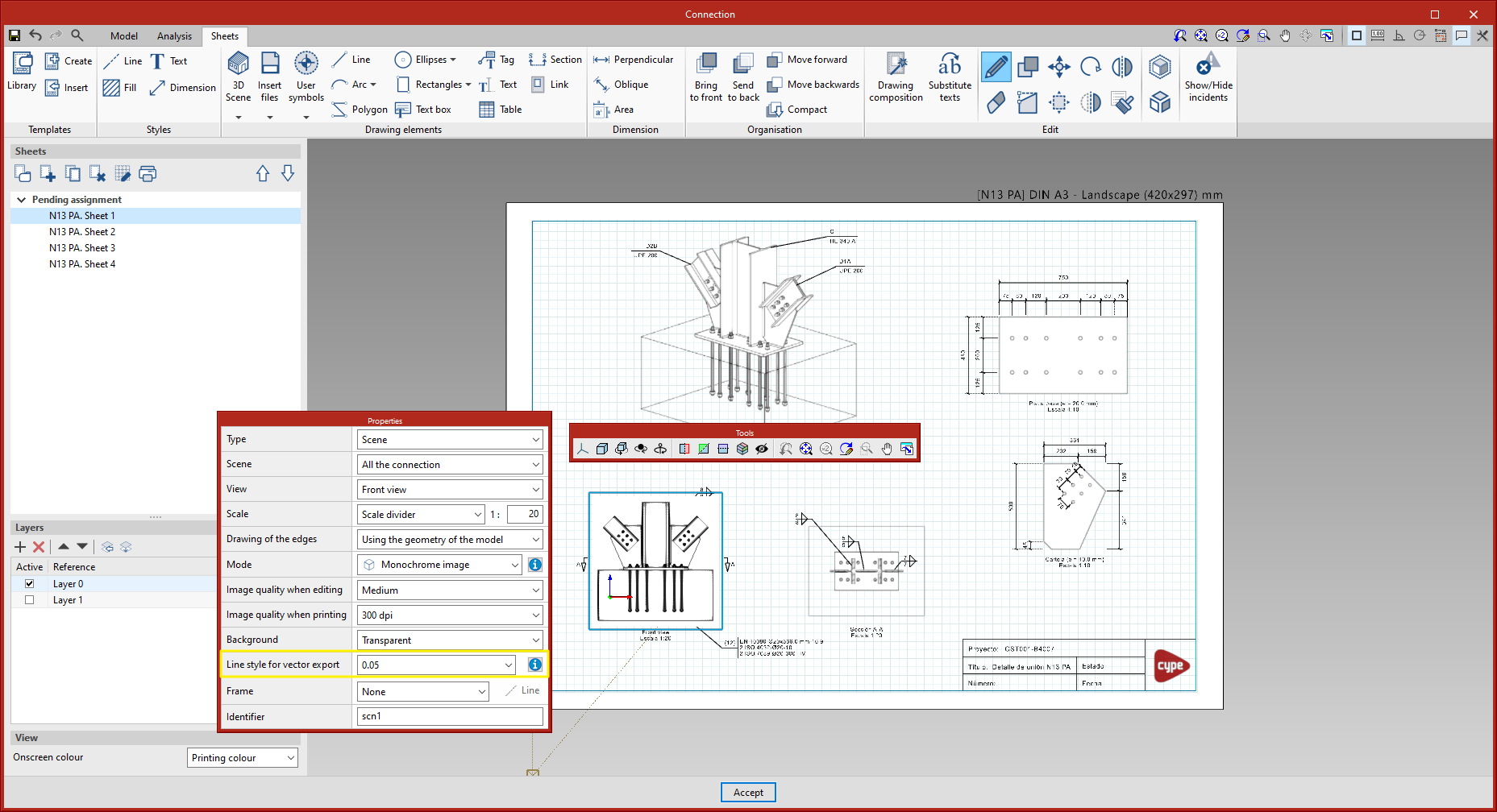
Vector graphics format export of 3D scenes
The option to export the 3D scenes in sheets in vector graphics format has been implemented in version 2022.g. Up to version 2022.f, these scenes were exported as raster images.
From the scene editing panel, the line style to be used for vector graphics format export can be configured.
From the ‘Print’ dialogue box, the scene views can be exported:
- As raster image (option used until this improvement was implemented).
- As vector image (when possible).
The latter option must be selected to export in vector graphics format. In particular, this explains the "when possible" note in the option, a scene view is exported as a vector image if two requirements are met:
- The projection defined for the view is axonometric.
- The colour mode is monochrome.
As an example, there are two PDF sheets that can be downloaded, which have been exported in vector graphics format.
Linking tags and dimensions to the geometry of the elements
The dimensions defined in each sheet are associated with the geometry of the elements of the scene that have been taken as a reference. This association allows the dimensions of the model to be automatically readjusted in the event of changes in the dimensions of the model.
In the particular case of the tags, this association was already maintained in previous versions, except in the particular case of the tags of the holes in CYPE Connect. As of version 2022.g, this association is maintained, allowing the directrix of the tag to be moved when the position of the relevant hole changes. This is a special case, as the hole itself is not an object in the scene.
New paper formats
New paper formats have been added to CYPE Connect and Open BIM Layout:
- DIN B type
B0, B1, B2, B3 and B4. - ARCH type
ARCH A, ARCH B, ARCH C, ARCH D, ARCH E and ARCH E1.
CYPE Connect
Shells associated with the connections library
As of version 2022.g, the connections exported to the connections library will also save their defined sheets. Thanks to this implementation, the work spent on making a detail drawing of a connection can be used for similar connections when applying a library connection.
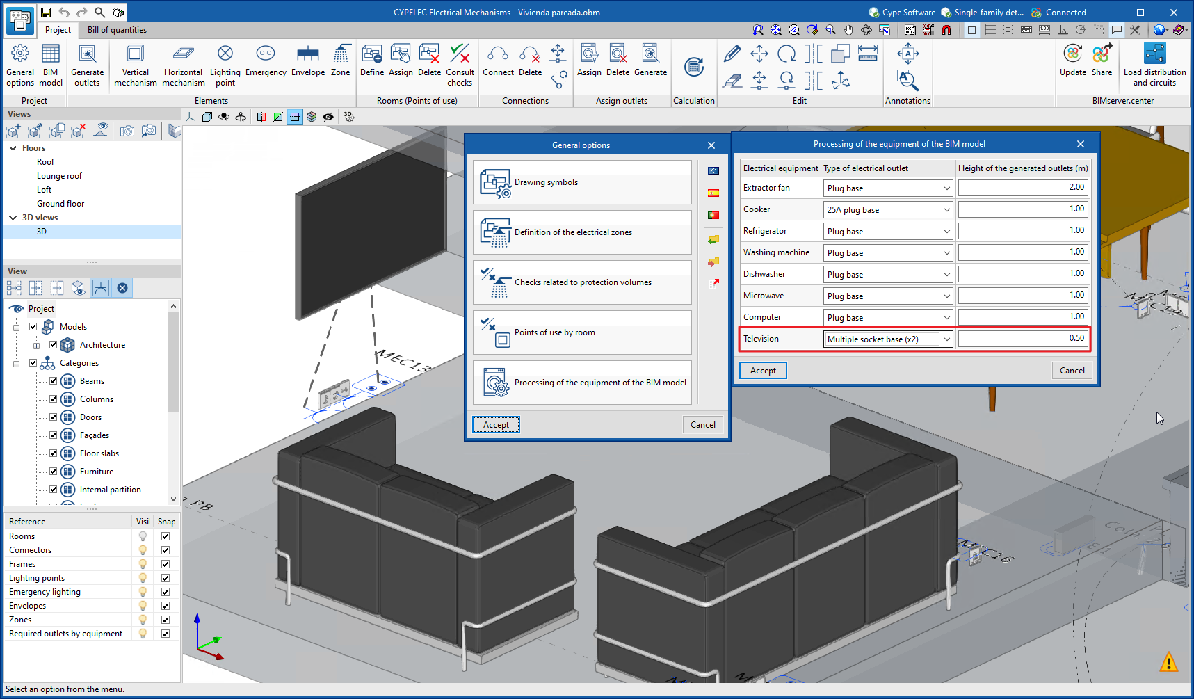
CYPELEC Electrical Mechanisms
Multiple socket base in the services required by equipment imported from the BIM model
The possibility of selecting a multiple socket base to power the equipment imported from the BIM model has been added.
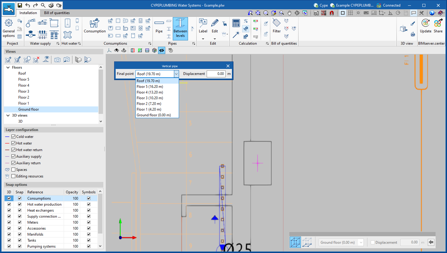
CYPEPLUMBING Water Systems
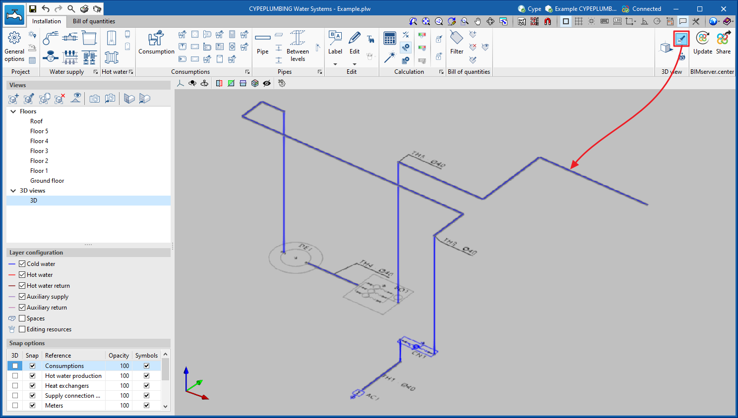
New 3D work environment
CYPEPLUMBING Water Systems is shifting from a 2D environment to a new 3D work environment, achieving greater capacity in the modelling of pipes and elements in water supply systems.
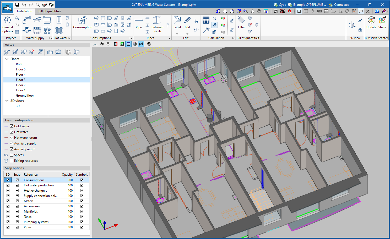
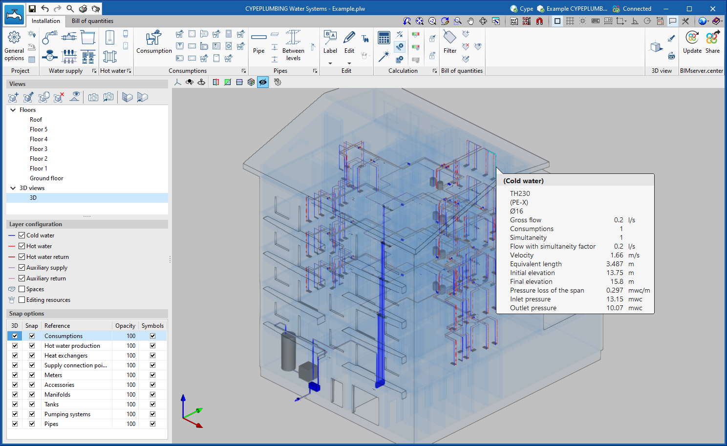
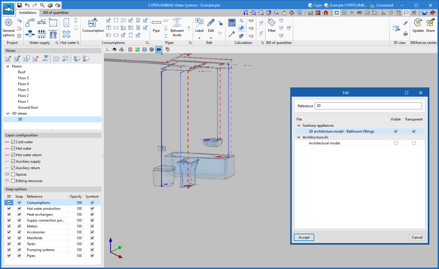
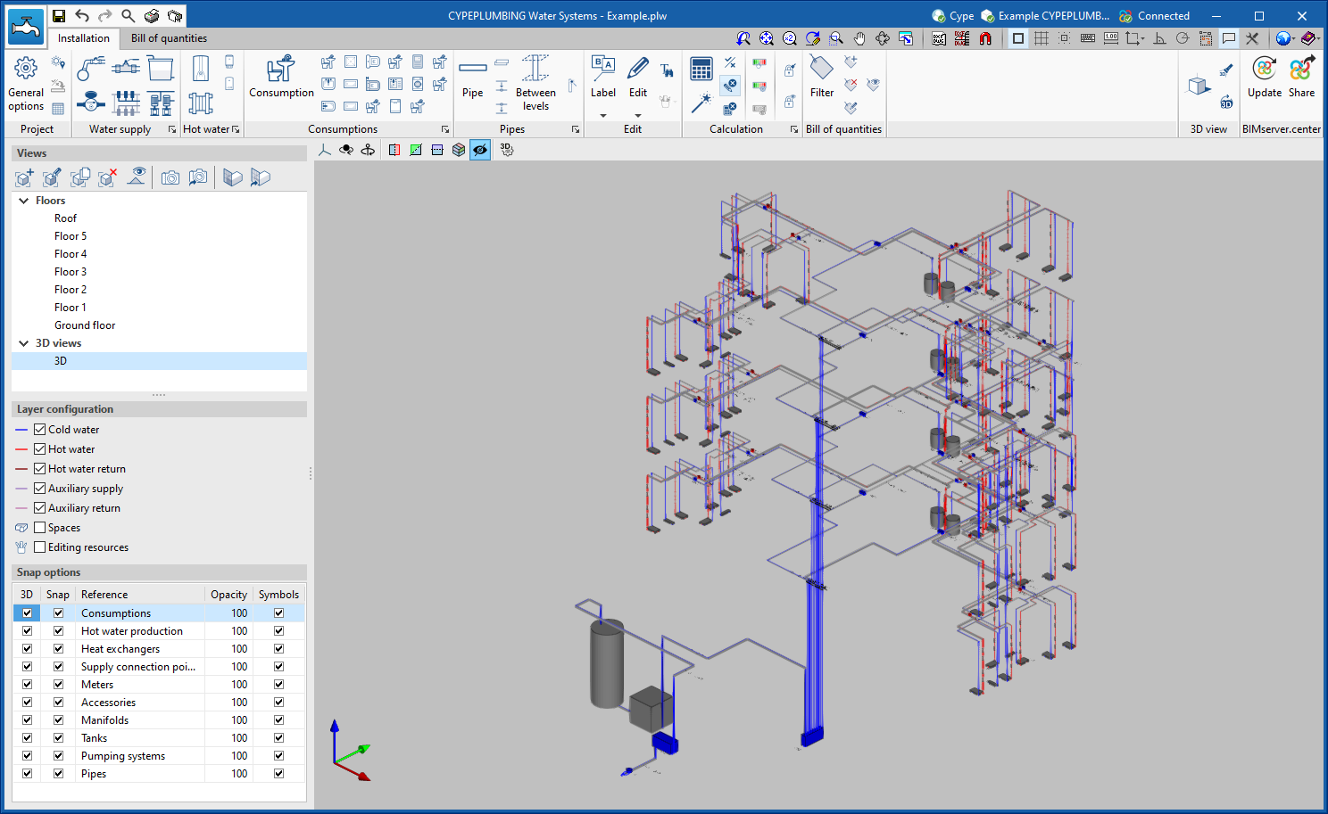
The new 3D work environment provides:
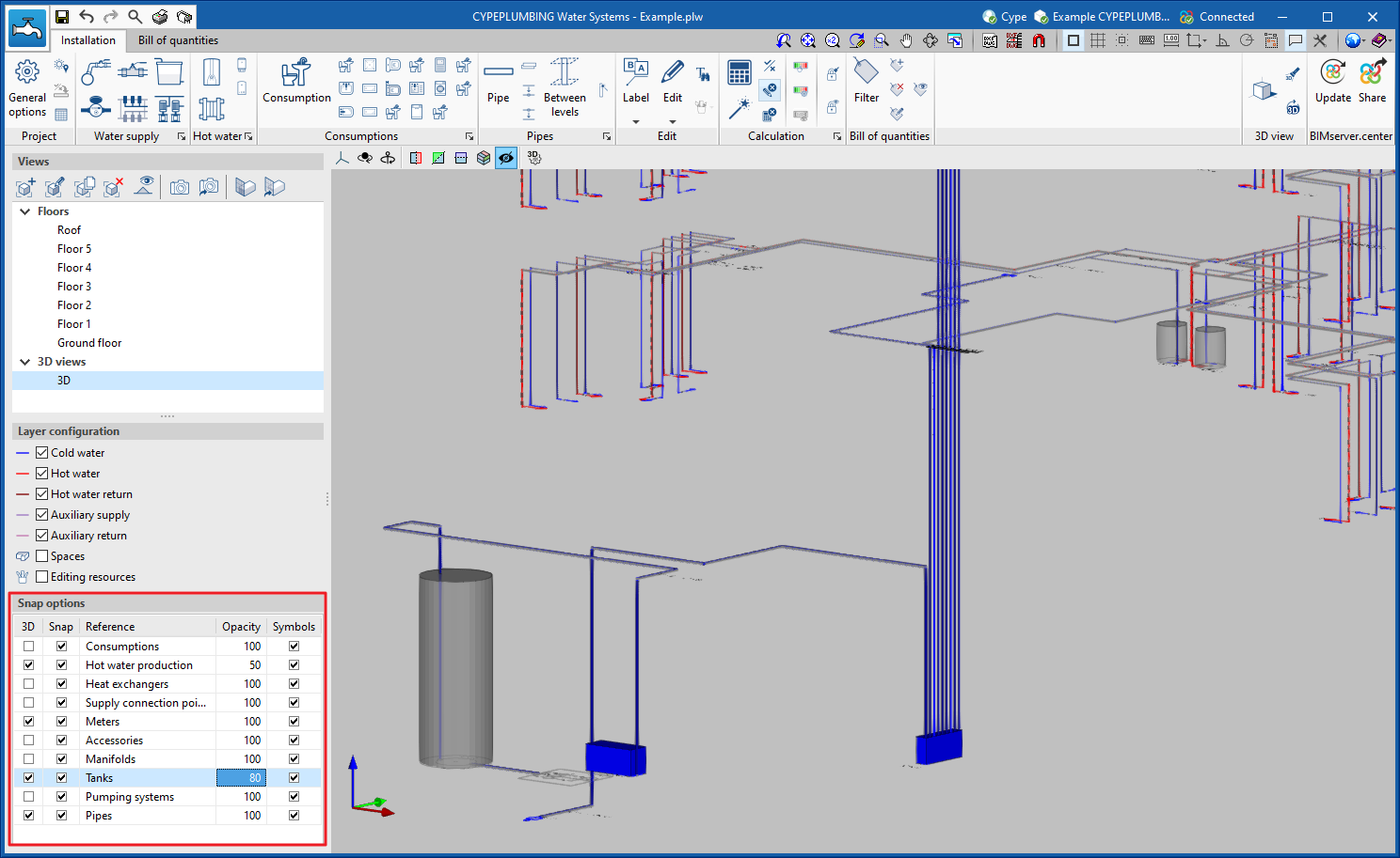
- A visualisation of the "3D Views" with symbology and representation of the 3D elements, along with the possibility to control their opacity level.
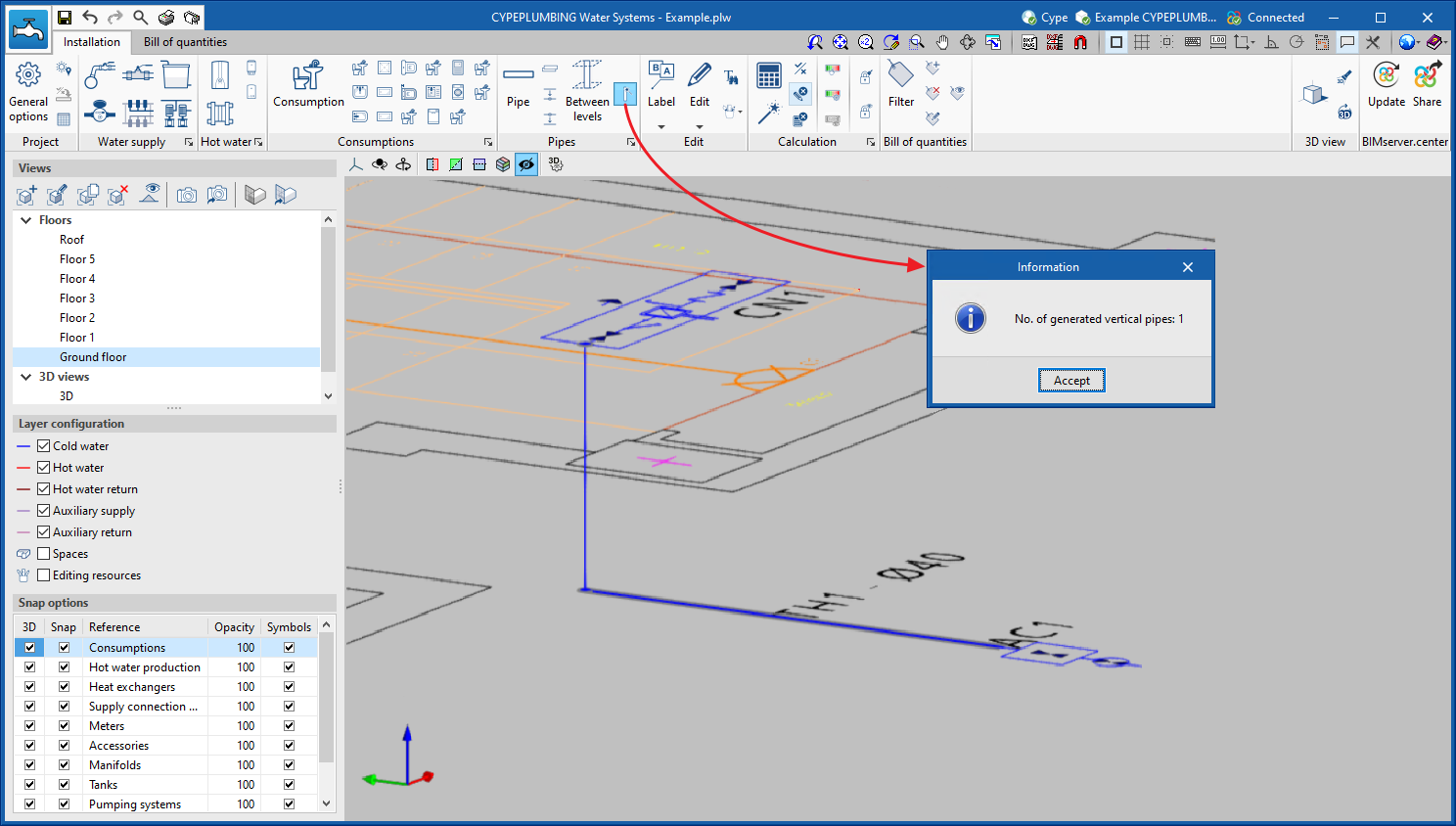
- The chance to enter all elements and pipes in 3D view or by floor. Vertical pipes in particular are now easier to generate.
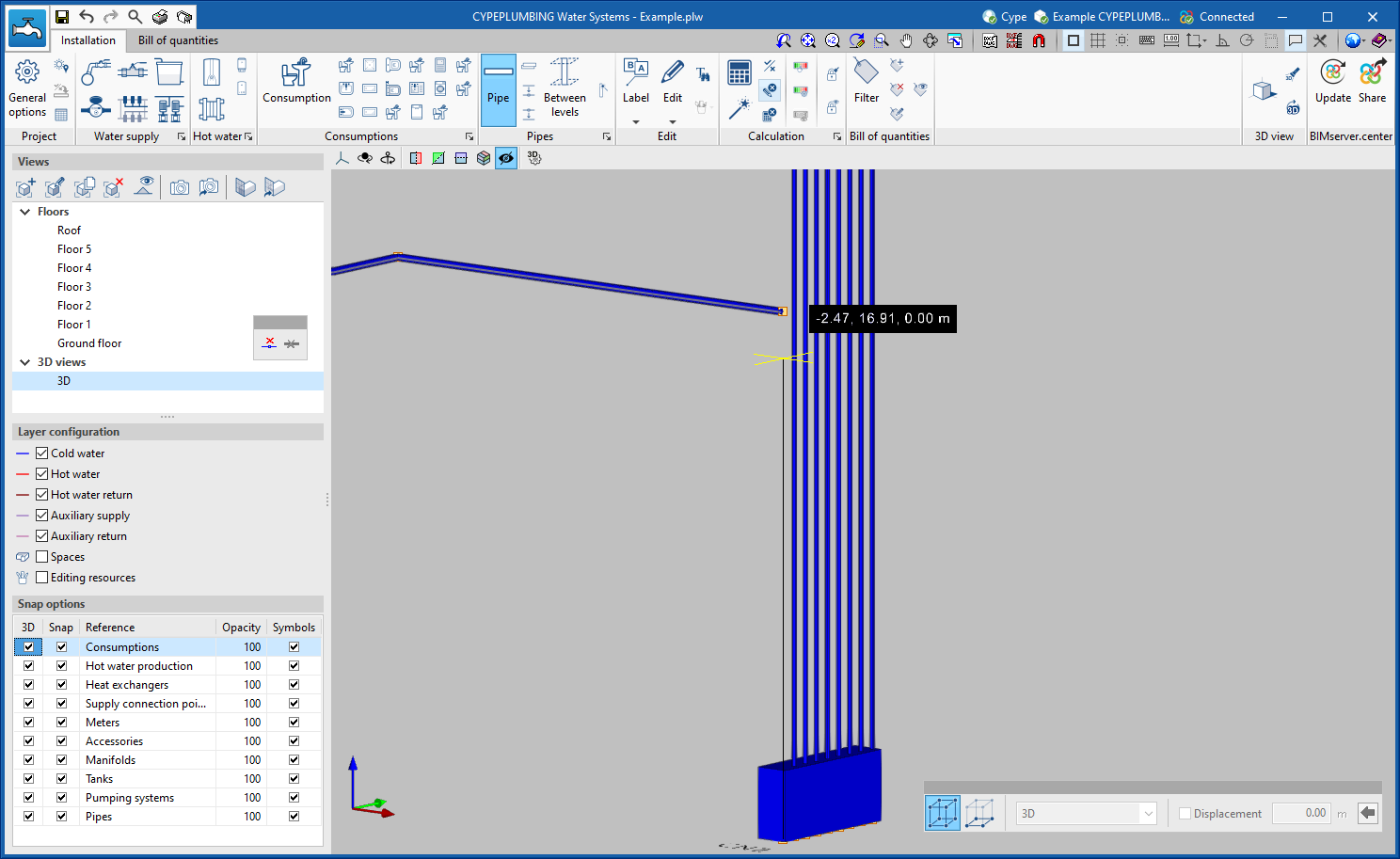
- Generation in 3D view
- Generation by floors
- Generation being edited or analysed
- Greater geometric precision when placing pipes and elements in the system. Users can define several levels of displacement in the system.
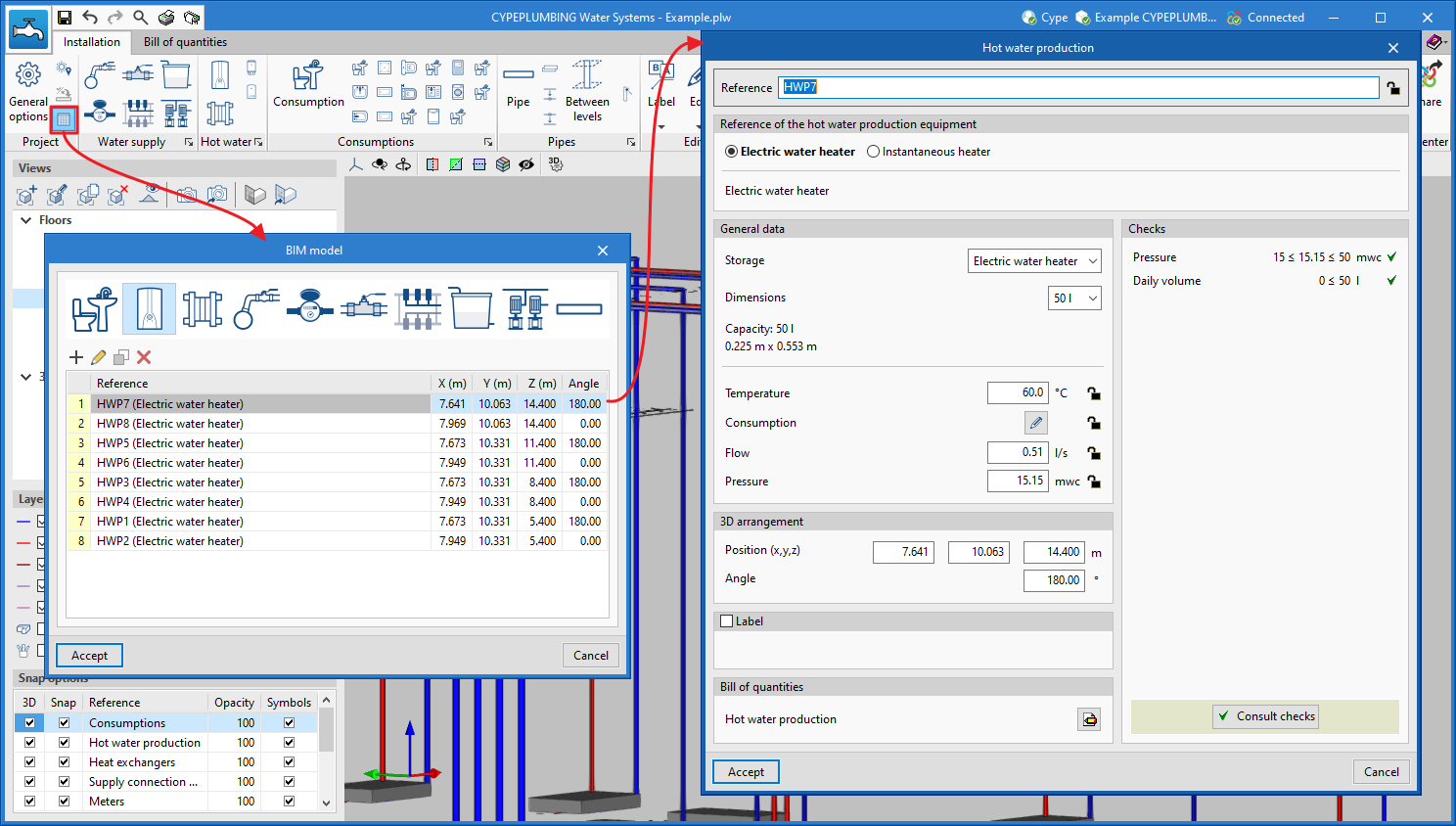
- The possibility to work on the table containing all the elements and pipes generated in the system.
- The possibility to work by viewing areas of the system.
- The extraction of 3D View planes containing information.
CYPEHVAC Ductwork
Direct links to other applications
In version 2022.g of CYPEHVAC Ductwork, new direct links to the Open BIM programs URSA AIR, Open BIM MOVAIR and Open BIM ISOVER have been implemented. These links can be consulted in the BIMserver.center section of the program’s top menu, which is available in the "Installation" tab.
Open BIM Quantities
Properties and quantities in the groups of the project tree
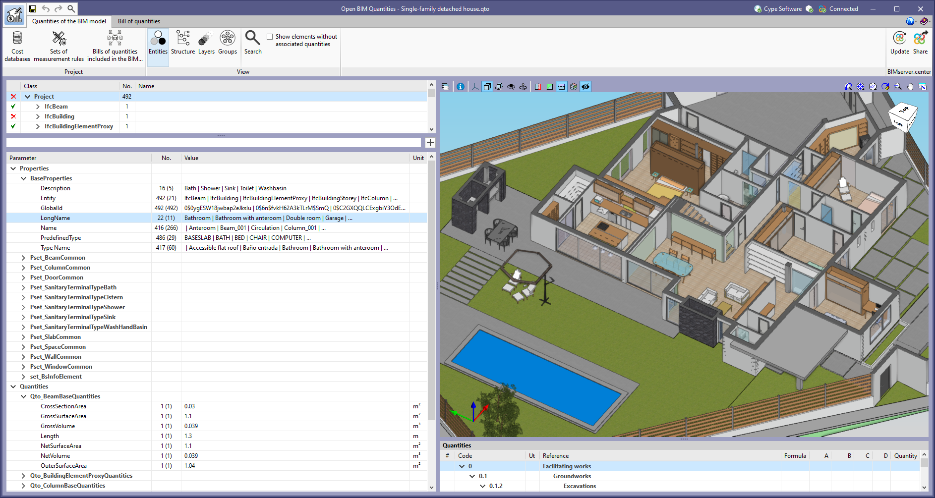
In the tree of entities in the BIM project, available from the "Quantities of the BIM model" tab in Open BIM Quantities, entities containing other elements can be found. These are represented in bold and can be expanded to show their content.
From version 2022.g onwards, when selecting an element composed of other elements in the tree of entities in the BIM project, the properties and quantities available in these components can be displayed. In this case, the "Value" column of the list of properties and quantities displays some of the values of the property or quantity that the components possess, separated by the "|" character.
Number of entities, properties and quantities
In the "Quantities of the BIM model" tab in Open BIM Quantities, the "No." column has been added to the tree of entities that make up the BIM project, as well as in the properties and quantities associated with each component. In the tree of entities, this field indicates the number of elements contained in each branch. In the case of properties and quantities, this field indicates the number of properties and quantities of the same type that are contained in the components of the selected element in the tree of components. Additionally, the number of unique values of the property or quantity is shown in brackets.

The "No." column can also be found in the list of properties and quantities that appears when using the tool available in Open BIM Quantities for facilitating the introduction of a variable in the comments of an item or in its quantities.
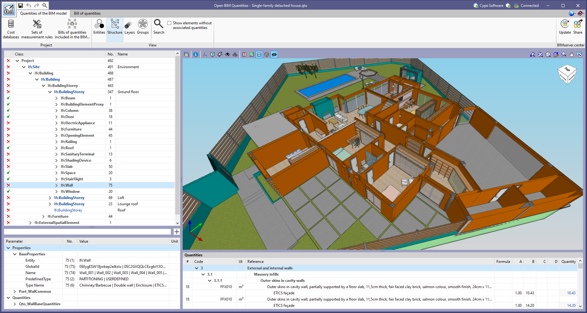
Quick rules reference
As of version 2022.g, when creating a quick rule for a property or quantity, the value of the property or quantity will be assigned as the rule reference. This way, a name is generated according to the entities of the IFC model that it contemplates.
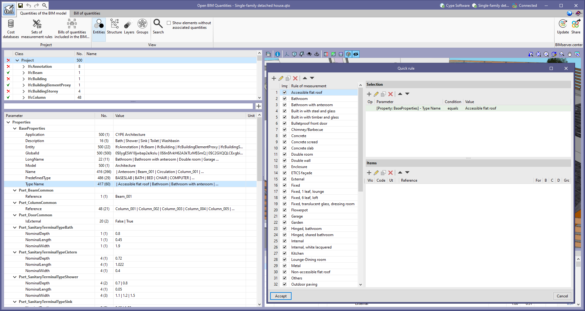
Quick rules on various properties or quantities
As of version 2022.g, when creating a quick rule on a property or quantity of a group of project elements (See "Properties and quantities in the groups of the project tree"), a rule will be added for each unique value of this (See "Number of entities, properties and quantities"). Thanks to this improvement, a complete quantity criteria can be generated from a property of the IFC model.